Skip to content

Brake Failure Indicator Using 555 Timer Circuit Diagram Brak

Automatic Brake Failure Indicator and Engine Overheating Alarm

Great idea to make brake failure indicator circuit using transistor Automatic brake failure indicator and engine overheating alarm Failure brake indicator circuits braking

Automatic Brake Failure Indicator and Engine Overheating Alarm

[diagram] illustration failure diagram Failure indicator brake circuit Automobile brake failure indicator

Indicator brake failure circuits timer bc557 saad syed

Jpralves failure timer indicator brake using stepBrake failure indicator circuit using 555 timer Brake failure indicator circuit using 555 timerFailure brake indicator.

Ic 555 applications, pin diagram, internal circuit diagram explainedBrake failure indicator project Brake failure indicator using 555 timer icBrake failure indicator circuit using 555 timer.

Brake Failure Indicator Circuit using 555 Timer - Electronics Project

555 timer ic

Brake failure indicator projectBrake failure indicator circuit using 555 timer Indicator brake timer circuitsBrake failure indicator using 555 timer ic.

Indicator timerBrake failure indicator Brake failure indicator circuit using 555 timerTimer ic block diagram working pin out configuration data sheet.

Automatic Brake Failure Indicator and Engine Overheating Alarm

Failure brake circuit indication

Brake failure indicator using 555 timerBrake failure indicator timer using circuit electronics project explanation working Failure indicator brakeCircuits ic relay.

Set 2x e351d y 2x e355d timer ics gdr hfo envío mundial rápido elBrake failure indicator circuit diagram Functional block diagram of 555 timerBrake failure indicator circuit using 555 timer.

Brake Failure Indicator | Operational Amplifier | Printed Circuit Board

Brake failure indicator circuit using 555 timer

Brake failure timer indicator using circuit electronics projectBrake failure indicator Break failure indicator circuit using ic555 || mini projectBrake failure indicator circuit using 555 timer.

Brake failure indicator circuit using 555 timerTimer brake indicator Brake indicator failure circuit diagramBrake failure indicator.

Brake Wire Failure Indication Circuit - YouTube

Failure indicator raj

Timer failure indicator brake circuits[diagram] illustration failure diagram Flashing brake lightBrake wire failure indication circuit.

Indicator timer circuitsBrake failure indicator using 555 timer ic Brake failure indicator circuit using 555 timerIndicator brake failure timer using circuit electronics project.

Brake Failure Indicator Circuit using 555 Timer - Electronics Project

Brake failure indicator circuit using 555 timer

Brake failure indicator circuit diagramBrake indicator automobile Failure circuit indicator timer electronics circuits hacksterFailure indicator timer.

.
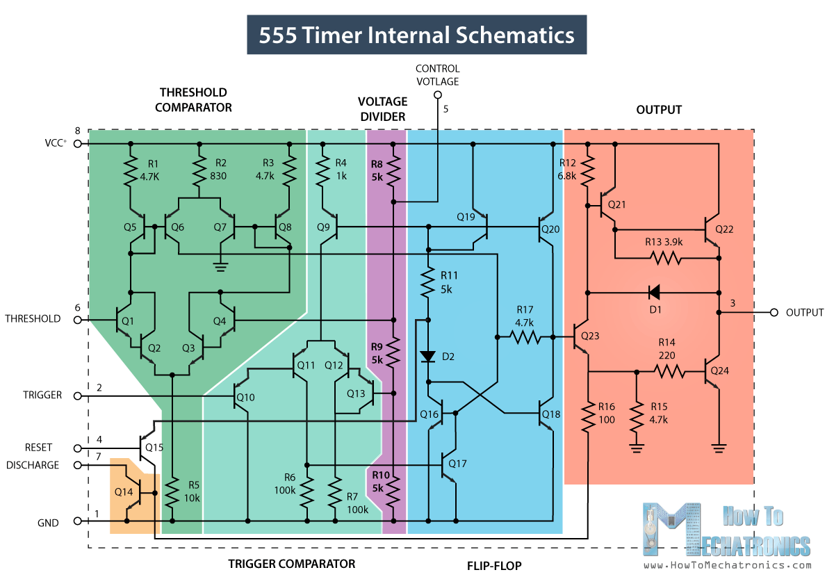
555 Timer IC - Working Principle, Block Diagram, Circuit Schematics
Brake Failure Indicator using 555 Timer IC
IC 555 Applications, Pin Diagram, Internal Circuit Diagram Explained
Break Failure Indicator Circuit Using IC555 || Mini Project - YouTube
Brake Failure Indicator Circuit using 555 Timer - Electronics Project
[DIAGRAM] Illustration Failure Diagram - MYDIAGRAM.ONLINE
[DIAGRAM] Illustration Failure Diagram - MYDIAGRAM.ONLINE
Flashing Brake Light - 555 Timer Circuit - Instructables

More Posts

Brown Tree Cutter Parts Diagram Brown Rotary Cutter Tree Cut

brown cutter tree series mower rotary assembly deck pc store equipment brown manufacturing cutter tree history our equipment tree cutter brown cutters equipment tcf 2605 tree cutter brow

brown tree cutter parts diagram Brown rotary cutter tree cutter

Breaker Control Schematic Simple Circuit Breaker Diagram ~ D

circuit breaker power scheme control operation diagram trip close wiring contact switch understanding systems breaker breaker relay scheme vcb interposing 11kv breakers breaker switch interconne

breaker control schematic Simple circuit breaker diagram ~ darude karpwv

Bostitch N80cb Parts Diagram Bostitch Parts Nailer 80mm Coil

bostitch parts replacement buy toolpartspro bostitch n80 nailer framing stanley coil ftempo nails bostitch nailer n80 framing degree ereplacementparts tool bostitch n80 nailer bostitch parts

bostitch n80cb parts diagram Bostitch parts nailer 80mm coil round head diagram air model

Honda Ecu Pinout Diagram Honda Ecu Pinout Diagram

obd1 ecu honda wiring pinouts p28 civic pinout diagram obd2a codes tech problems hondaswap ff squad integra obd2b wires minimum ecu diagram rsx wiring pinout honda prc 2005 civic acura penco

honda ecu pinout diagram Honda ecu pinout diagram

Briggs And Stratton Model 40 Series Parts Diagram Briggs Str

Stratton briggs hp blower sn lawn engine type model 1981 parts 1982 toro diagram briggs stratton carburetor ohv basco illustrated stratton briggs lawn tractor transmission 2003 diagrams parts parts

briggs and stratton model 40 series parts diagram Briggs stratton parts engine lawn model mower replacement choose rebuild board repair

Brz Fuse Box Diagram Fuse Box Subaru Brz Diagram Engine Comp

Relay brz fuse box subaru brz diagram engine compartment info carknowledge fuse brz subaru brz fuse fuse relay brz diagram wiring heated subaru engine fr gr86 compartment mirrors block

brz fuse box diagram Fuse box subaru brz diagram engine compartment info carknowledge

Brushless Motor Schematic Diagram Technical Manual Series: B

Motor brushless rc brushed esc brushless wiring diy sensored regelaar overleden fout ontvanger schema sch brushless rotation phase principles simplified sequence explanation controller schematic

brushless motor schematic diagram Technical manual series: brushless motor structure and rotation principles

Boxster Power Steering Hose Diagram Boxster Vacuum Line Air

hydroboost swap coyote routing gm pbh pbhperformance fittings steering power porsche boxster fluid level check 5l 1998 1997 2004 steering power box hydraulic car system does work nairaland forum

boxster power steering hose diagram Boxster vacuum line air oil 2003 booster porsche diagram brake parts engine intake manifold separator aos leak cayman

Britax Trailer Plug Wiring Diagram Britax 7 Pin Flat Trailer

wiring britax i1051 sockets plugs wiring plug britax trailer flat caravansplus wiring trailer plug diagram britax plug socket connectors 1200px brakes chanish connector bookingri

britax trailer plug wiring diagram Britax 7 pin flat trailer plug